Hull
In CADMATIC Outfitting, the Tools tab displays a Hull button for working with CADMATIC Hull. Before using the commands in this menu, make sure CADMATIC Outfitting has been set up to work with CADMATIC Hull. For details, see Hulltool profile.
Note: The Hull menu includes different commands for Hull Classic and Hull COS.
Hole list
Note: This command is not available when using Outfitting with Hull COS.
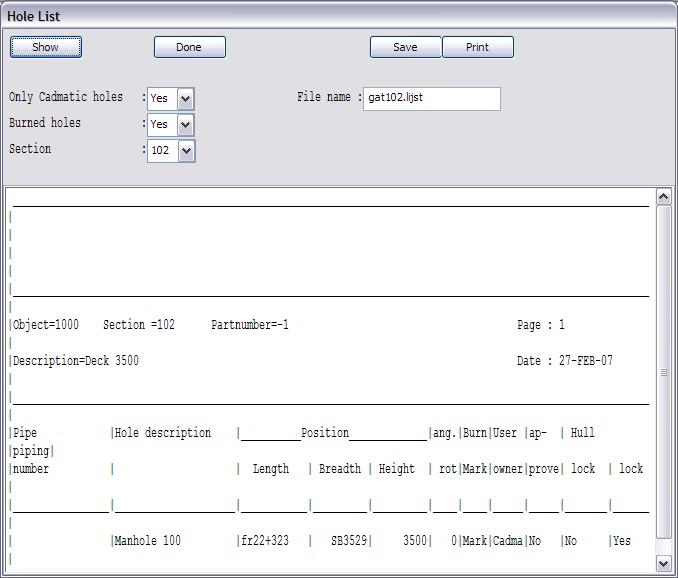
With this command you can generate a hole list from a section.
In the hole list panel you select following items:
- The section you want to create a hole list from.
- You can choose whether the list should contain only CADMATIC holes. If you select No, the list contains holes created by both applications CADMATIC Outfitting and CADMATIC Hull.
- You can choose whether the list should contain only Burned or only Marked holes.
- The hole list is generated with Show.
- You can save the hole list with Save. You can change the name of the hole list in the File Name field. The list is saved under your workspace under Plant Modeller area.
- You can print the hole list with Print.
Hull shape
Note: This command is not available when using Outfitting with Hull COS.
With this command you can retrieve the hull shape from CADMATIC Hull and show it in CADMATIC Outfitting.
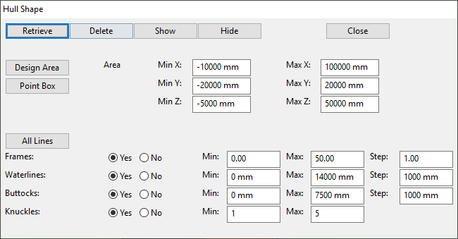
Retrieve – Get the hull lines from the hull shape database and show them in CADMATIC Outfitting.
Delete and Hide – Remove the existing hull lines.
Show – Show the lines which have already been retrieved.
These hull lines will be presented only in the area as shown in the dialog. You can choose to set the area limits equal to the Design Area limits using the button Design Area, or you can choose you own area box using the button Point Box. For example when you have chosen a small point box and retrieved the hull lines you will see all the hull lines in that box. With Delete and Show, you can let these line disappear and appear again. When you make the area-box bigger then you need to press retrieve to let also the lines to be shown in the extended area.
There are 4 types of hull lines:
- Frames
- Waterlines
- Buttocks
- Knuckles.
You must select the hull line type(s) which are presented. It is also possible to select which and how much lines of a certain hull line type should be presented using the fields: min, max and step.
Note: The hull lines are placed in the system "Hull Lines" (systemID 112).
Update from Hull
Note: This command is not available when using Outfitting with Hull COS.
This command will actually start the function from CADMATIC Hull and you use it to retrieve updates from Hull application. You can find more information about this tool from the CADMATIC Hull online help.
Coordinate references from Hull
With this command you can get the correct alternative coordinates from CADMATIC Hull into the CADMATIC COS server. In other words, the "Coordinate references" COS object is replaced with coordinates from CADMATIC Hull and then coordinates are used by CADMATIC Plant Modeller and/or CADMATIC Piping Isometrics & Spools.
This function will create the following:
- X Direction Planes for each of the frames in the Hull shape, with names starting with "FR"
- One Y Direction Plane for the center line of the ship, called "CL"
- One Z Direction plane for the base of the ship, called "BASE"
When the Hull project uses a NAPA shape database, only frames intersecting with the shape will be imported. When the Hull project uses a hullshape database (also referred to as HDB or IGES), all frames defined in the shape will be imported. Frames that do not intersect with the shape will result in a reference point instead of a plane, in the sense that the Y-range and Z-range are empty. None of the manually added grids (length, width, height, or arbitrary) are imported, only the length grid that comes from the shape.
Note: When using this command, the existing CADMATIC Hull X coordinate references will be replaced with the new ones.
Tools to modify this coordinate object or to create own definitions can be accessed via the Plant Modeller menu File > Environment > Coordinate references, the Piping Isometrics & Spools menu Settings > Project Administrator's Tools > Coordinate References > Create or Modify Coordinate References, or the Project Environment dialog.